


P R E A M B L E :
This plane was bought at a special price due to its being overweight (by a few hundred grams) for F3A competition.
Comments on the ARF delivery condition:
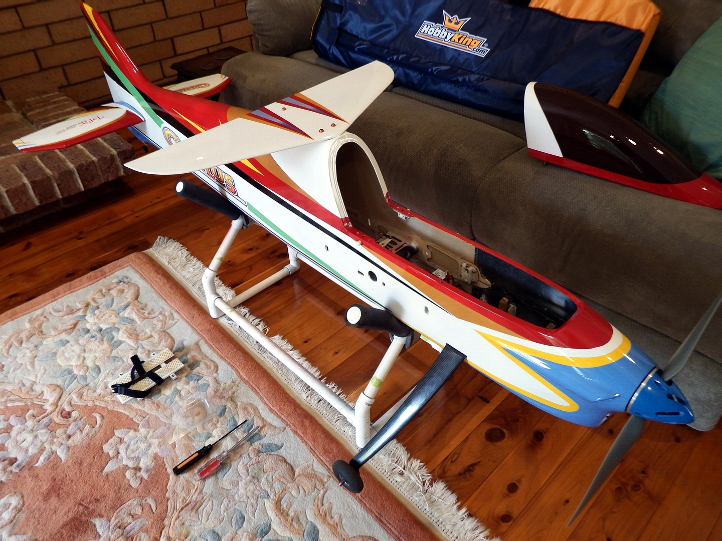
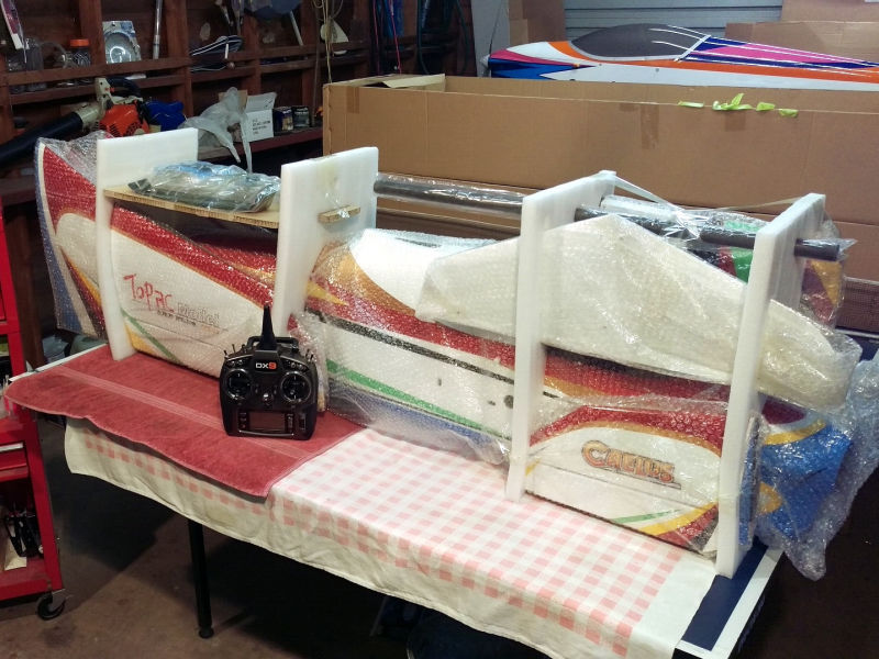
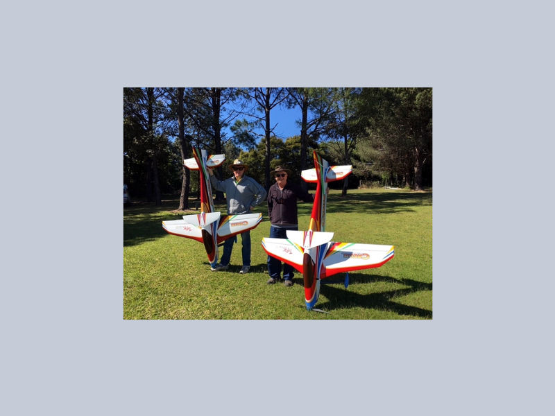
>>> Very well packed in an outer, thick casing and held firmly in place by foam formers and separators - see the photos below.
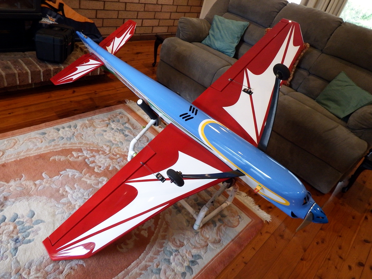
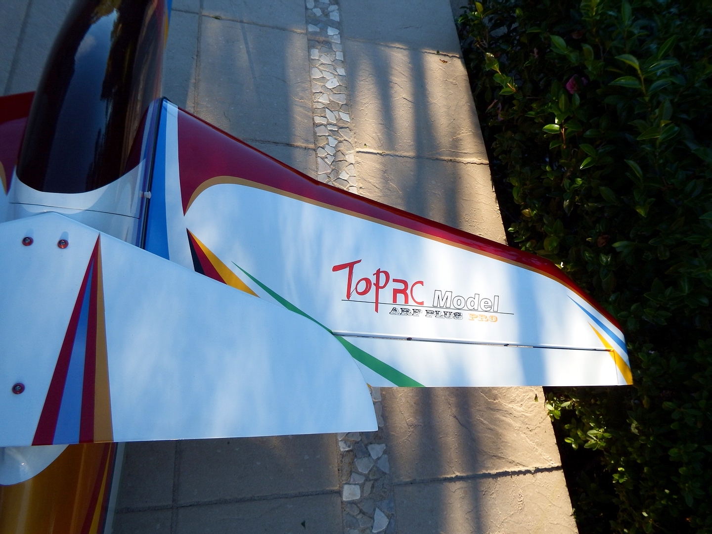
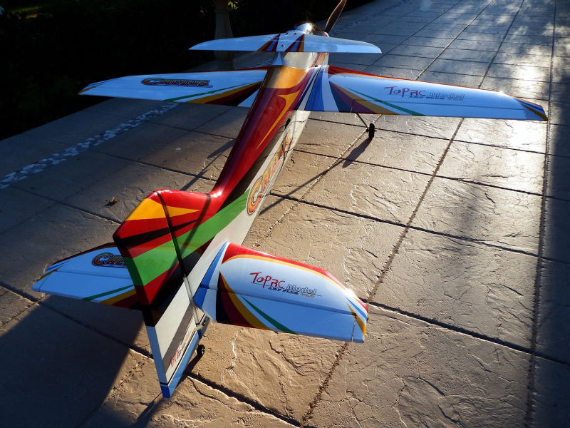
>>> The ailerons and/or the wings have slight twists in them resulting in the ailerons not fitting flush in their wing recesses. I ended up with the aileron outer ends slightly up compared to the wing profile. Fortunately, the twist was symmetrical across the two wings.
>>> The tail pieces, stabilisers and elevators, are very heavy!!
>>> In the cockpit zone:
>> The battery tray supplied is impossibly located necessitating the replacement of this component.
>> The wing incidence adjusters are not located at the same level!
>> There is no built-in motor mount.
B U I LD :
Power Considerations:
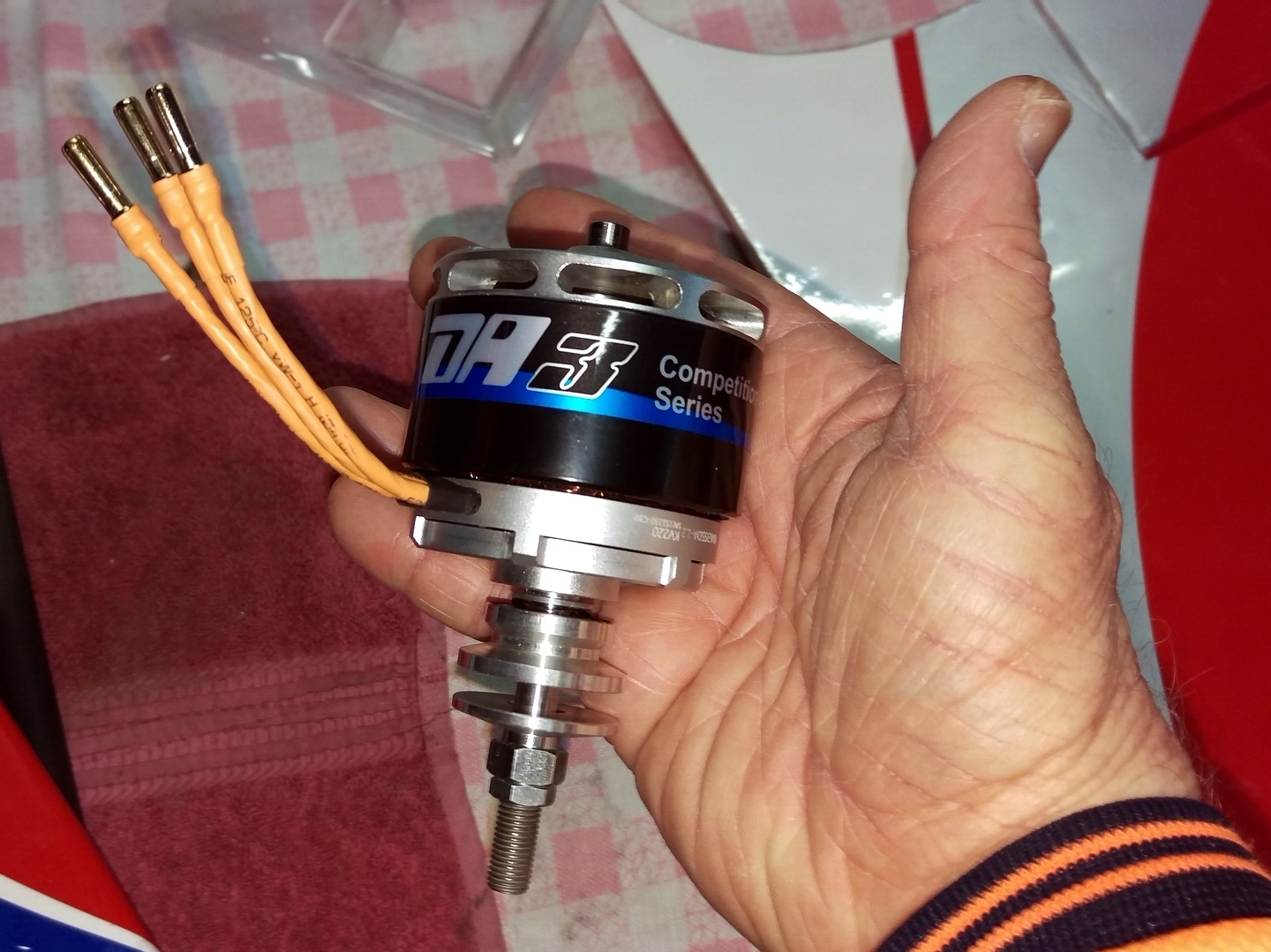
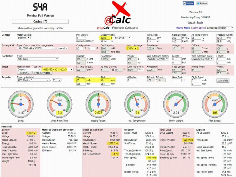
>>> Using 2 x 5S 5000 30C batteries, Dualsky XM6355DA-12 222Kv motor and 20x10 APC prop there is an expectation of around 2577watts power available - see the eCalc results posted in a photo below. The power to weight ratio of 585watts/kg allows for unlimited aerobatics.
Servos:
>>> The ailerons and rudder servos, Hitec HS-5485HB, fit well with minimal easing of recesses . The ball jointed push rod systems work well.
>>> The elevator servos, Hitech HS-485HB x 2, one in each stabiliser half, fit well with minimal easing of the in-stabiliser recesses. Each servo is driven by its own channel - easily done on the Spektrum DX9.
>>> All the servo horn outstands to push rods are kept short while the horn outstands at the control surfaces are kept longer. This maximises the firmness and positional resolution of the control surfaces.
Ailerons:
>>> The smallest, reasonable gap was maintained between the aileron and wing trailing edge. Robart style hinges are employed for all control surfaces.
>>> Ailerons are plugged into the Aile(right) and AUX1(left) channels. This allows for separate aileron setups.
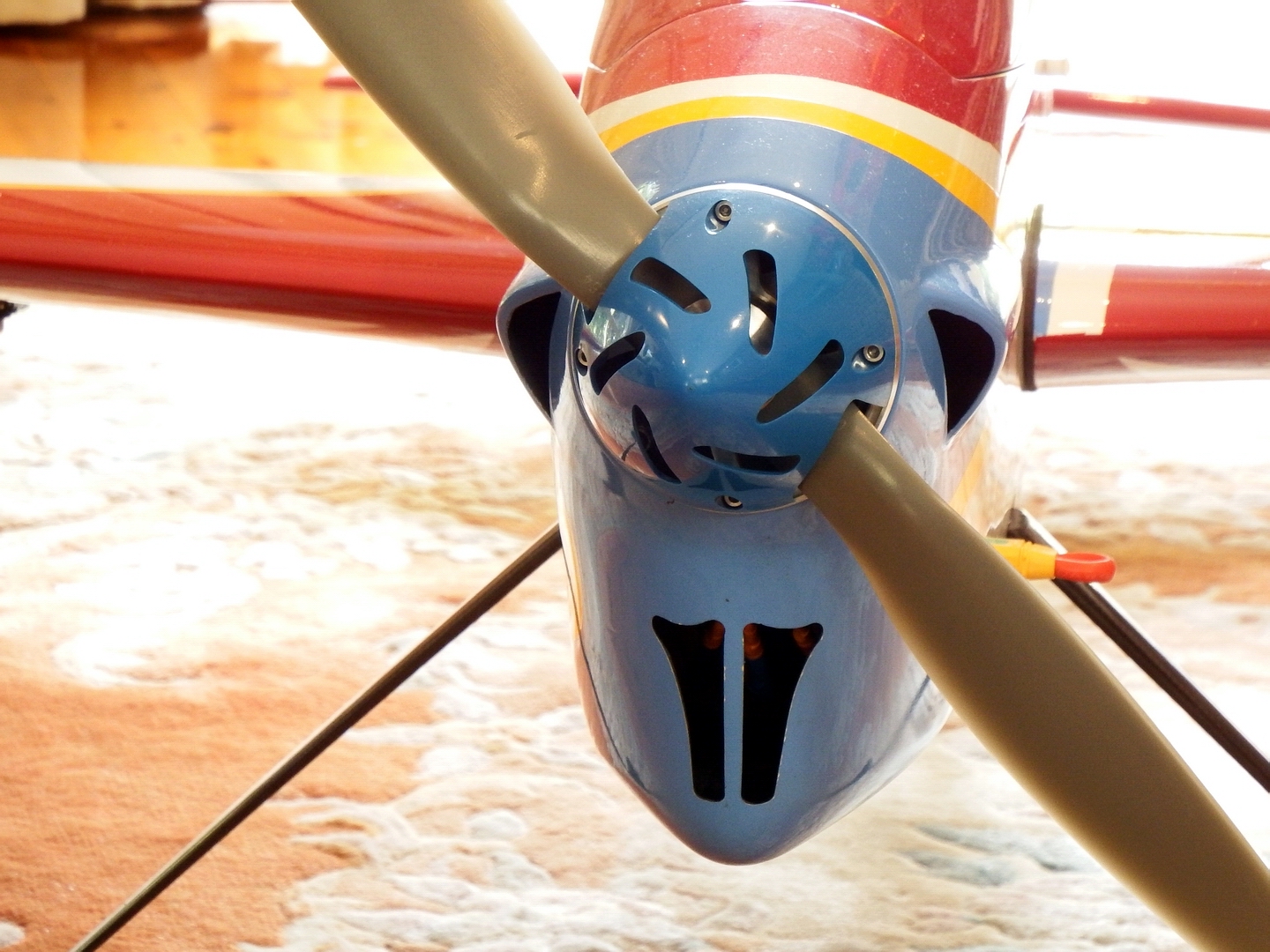
Stabiliser and Elevators:
>>> A single incidence adjuster is provided - accessed near the tail wheel mount. The stabiliser halves are screwed to and rotate on the rear, main joiner tube. The front, locating joiner is somewhat smaller and passes through the rear incidence adjuster.
>>> The two servos are plugged into Elev(right) and Gear(left) channels providing separate Tx setup for each elevator half. The DX9 Tx allows for this in its Aircraft Type setting.
Rudder:
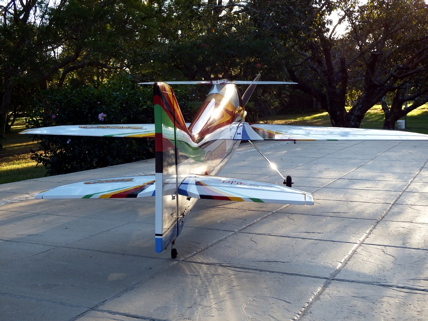
>>> The tail wheel assembly employs a torsion bar off the rudder to effect direction change. This ensures the rudder hinges never have to sustain impact loads.
>>> The driving servo is located in the cockpit zone. A wire pull-pull system operates the rudder.
>>> The tail wheel assembly is mounted into the fuselage tail and is additionally supported by a custom shaped wooden block. The first few flights showed that the wheel would eventually be pulled out of the fuselage by the rough runway conditions.
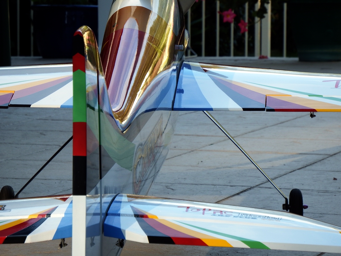
Undercarriage: (Bear in mind here that our local field has a grass, dirt and rabbit holed runway......)
>>> The provided wheels were put into stock and replaced with 3 inch Dubro Low Bounce wheels. These reduce running noise whilst on the ground. Matching stub axles were employed.
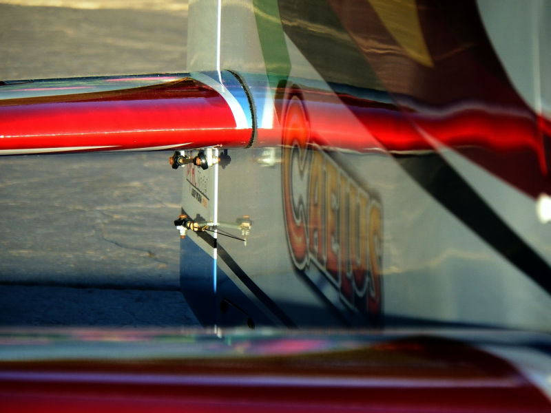
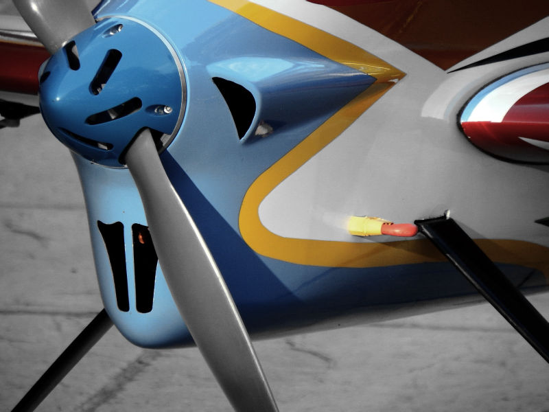
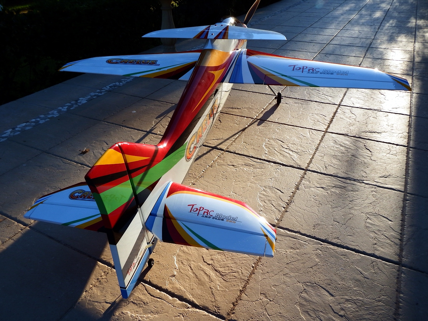
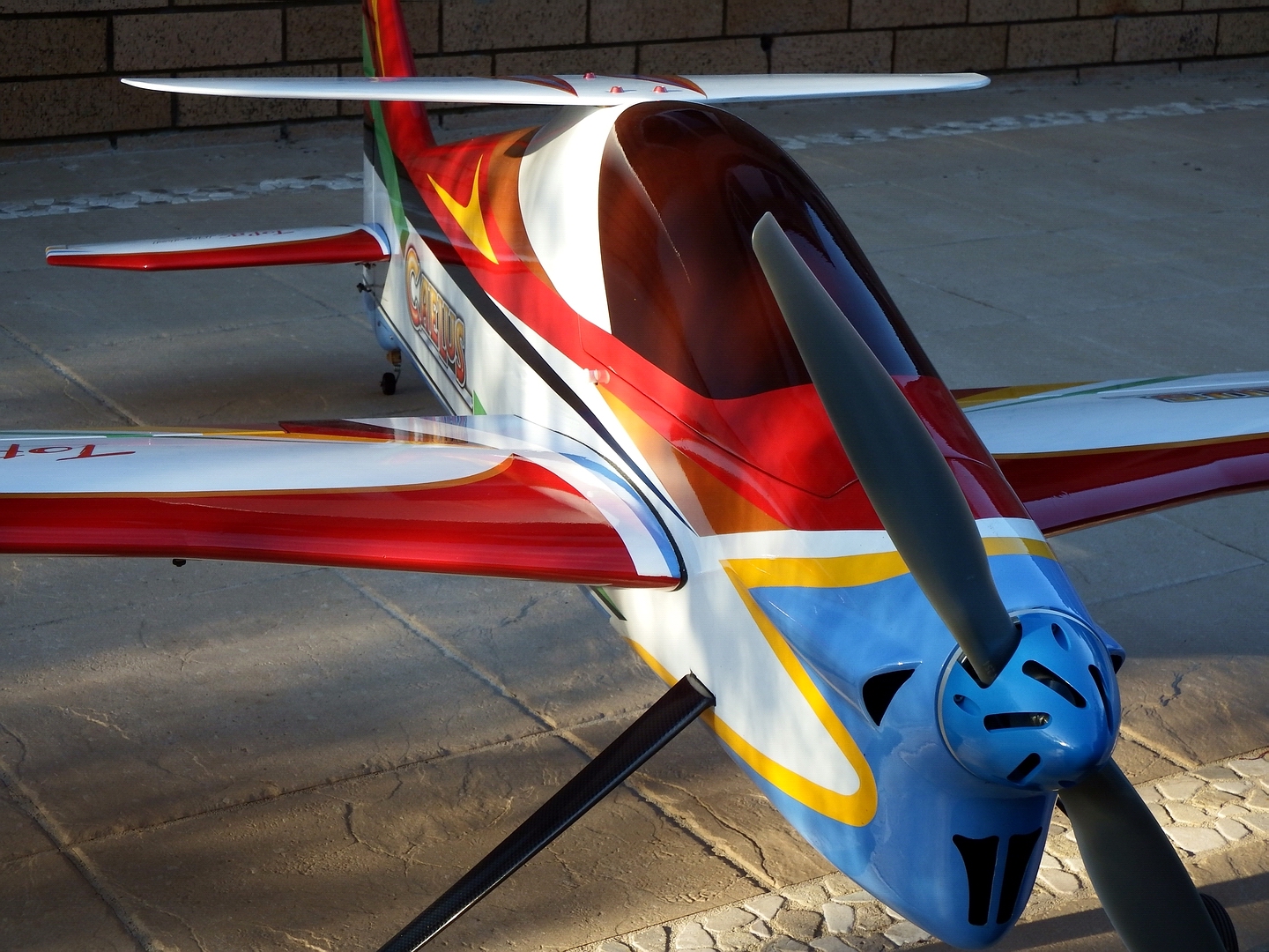
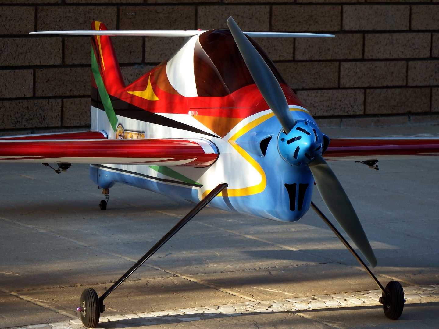
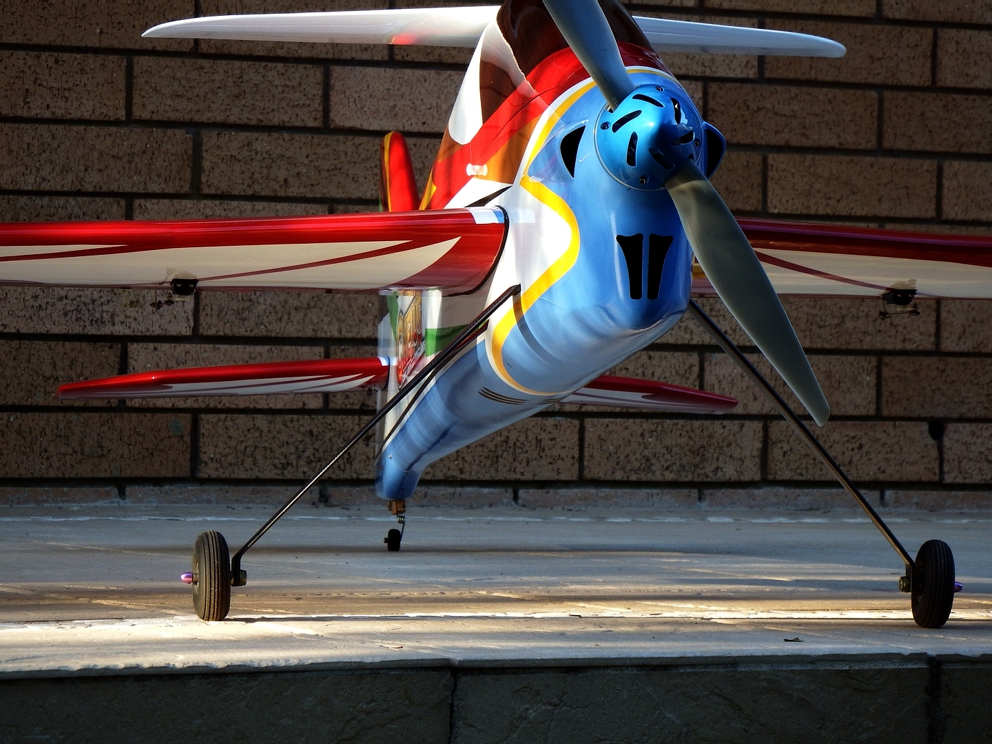
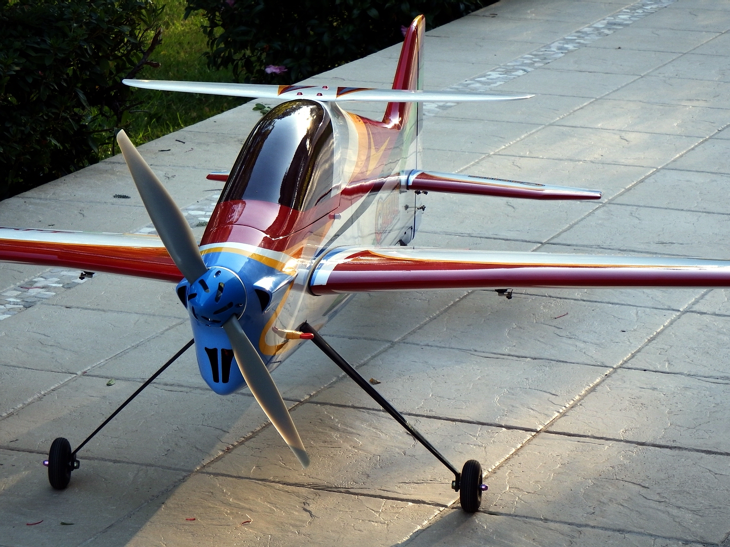
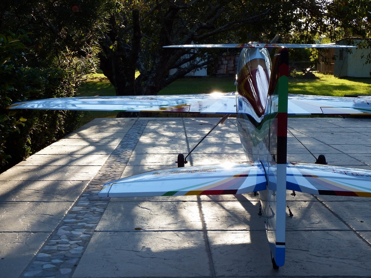
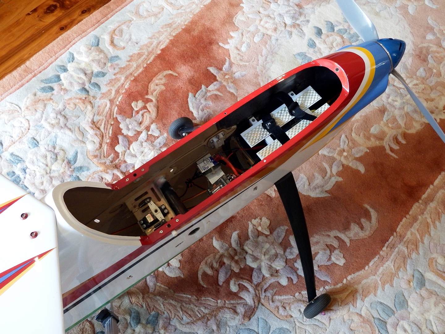
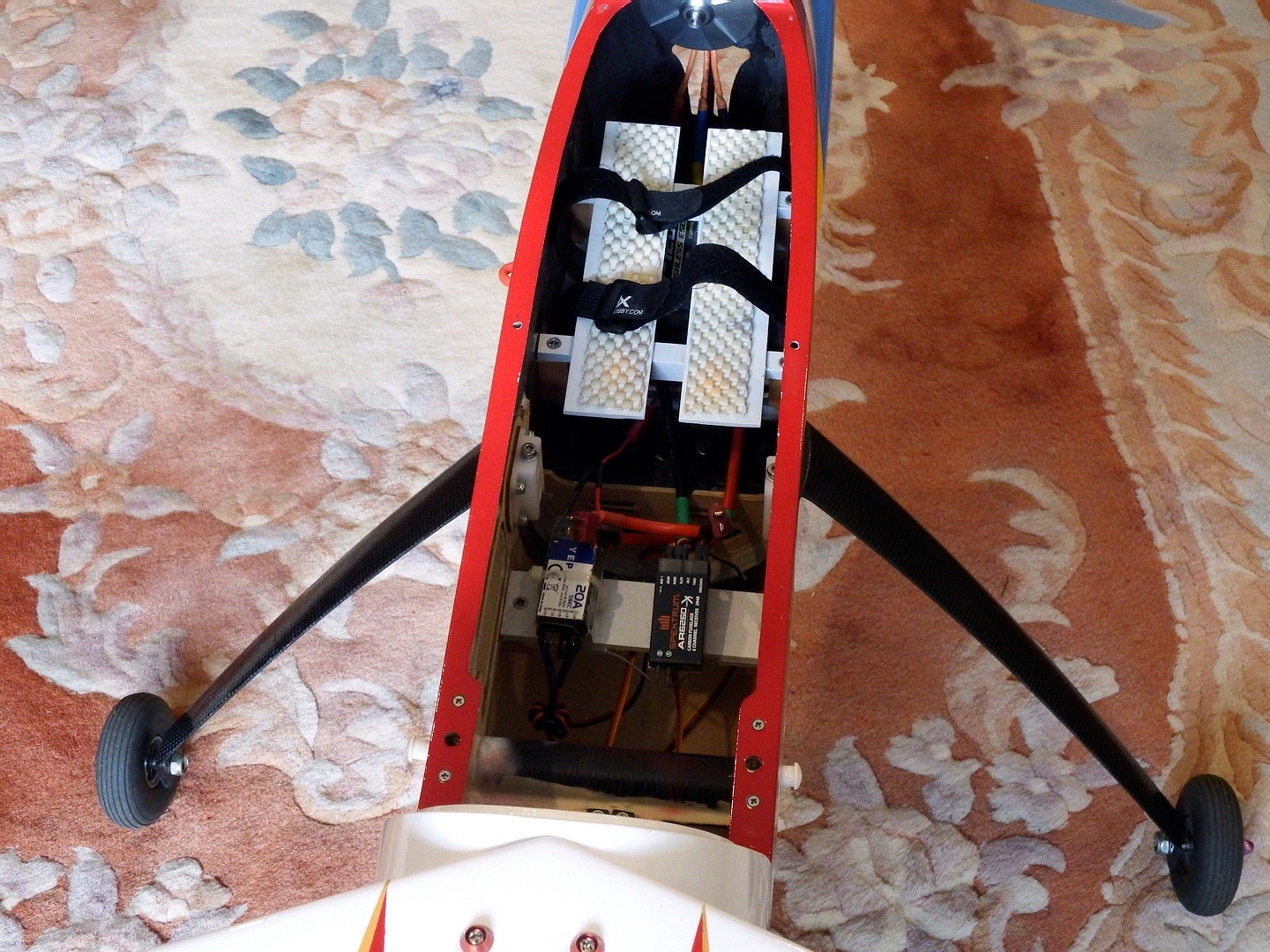
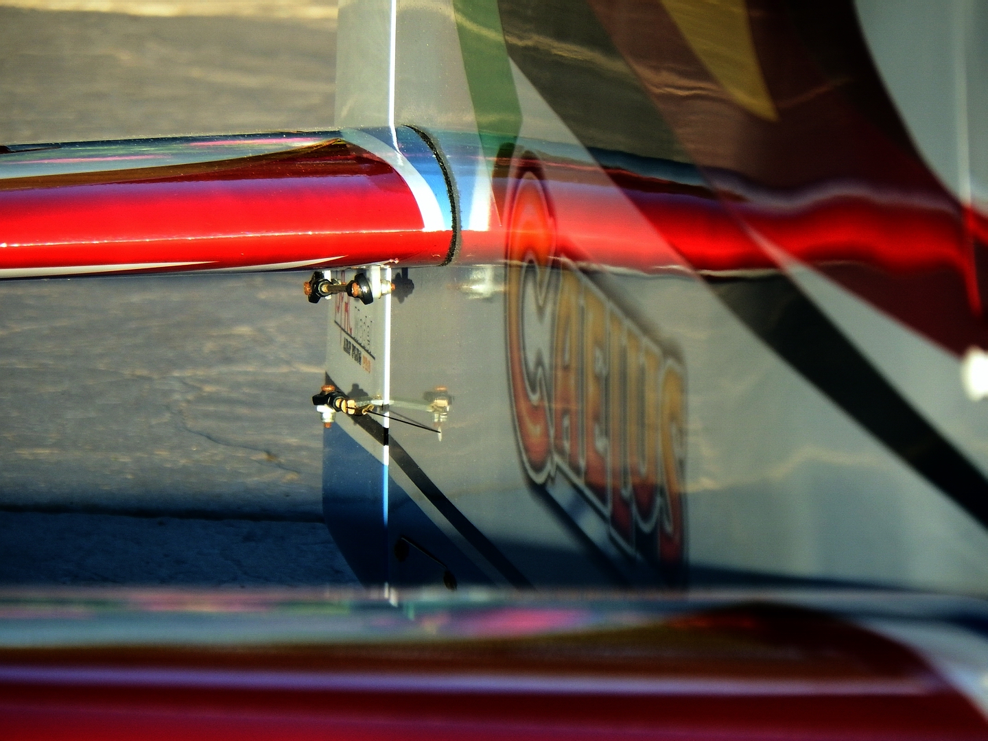
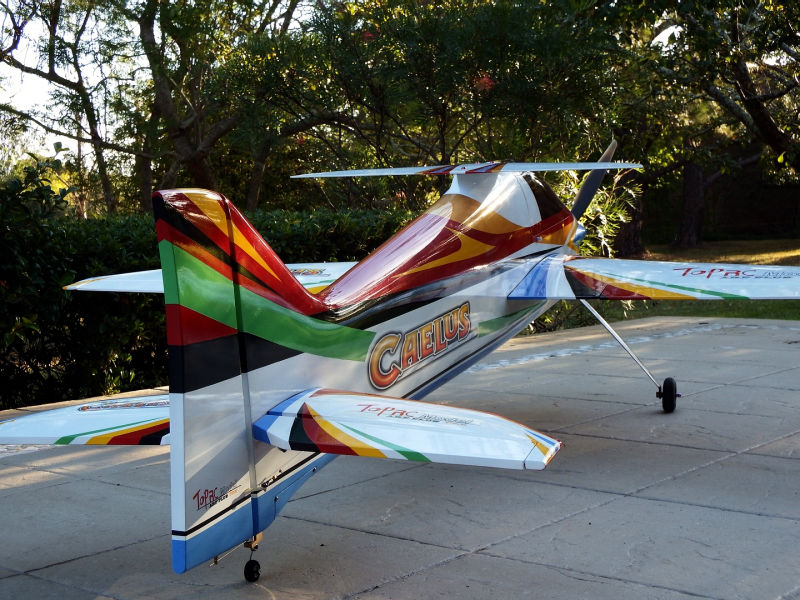
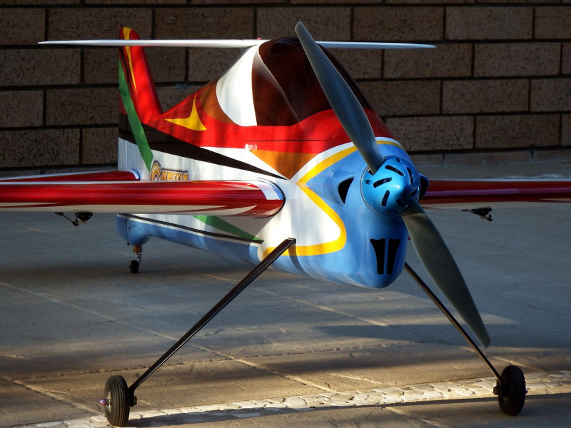
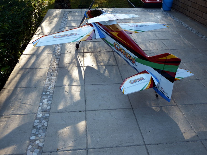
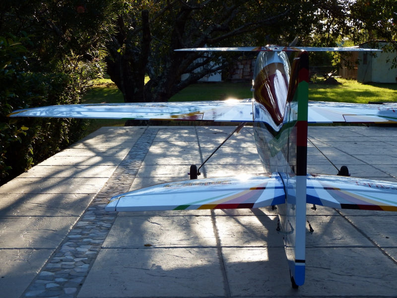
>>> A problem has arisen with the bolt-down of the undercarriage into the fuselage. The design employs just two bolts on the centreline of the upper end of the U/C legs. Even after being very firmly fastened down, the undercarriage has a tendency to rotate under load, the trailing edge of the legs lifting upward and crushing local fuselage. Check the artistic photos and particularly where the left side U/C leg enters the fuselage. Not yet determined a resolution for this problem.
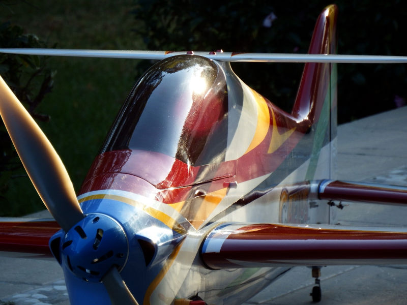
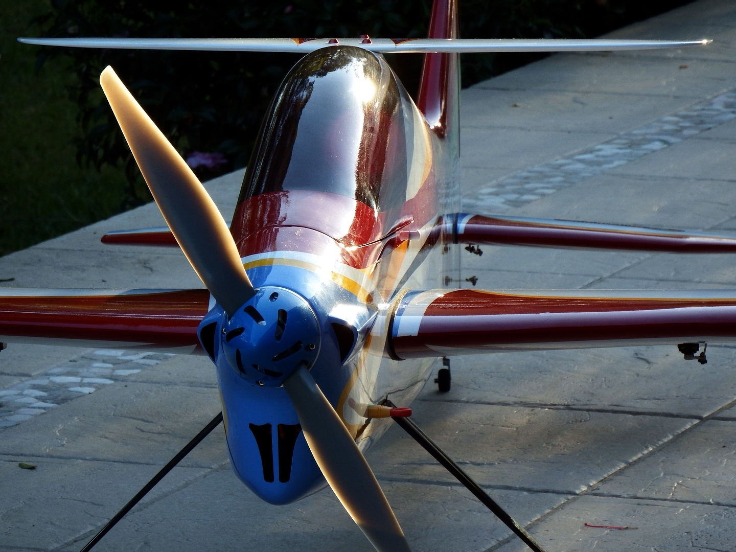
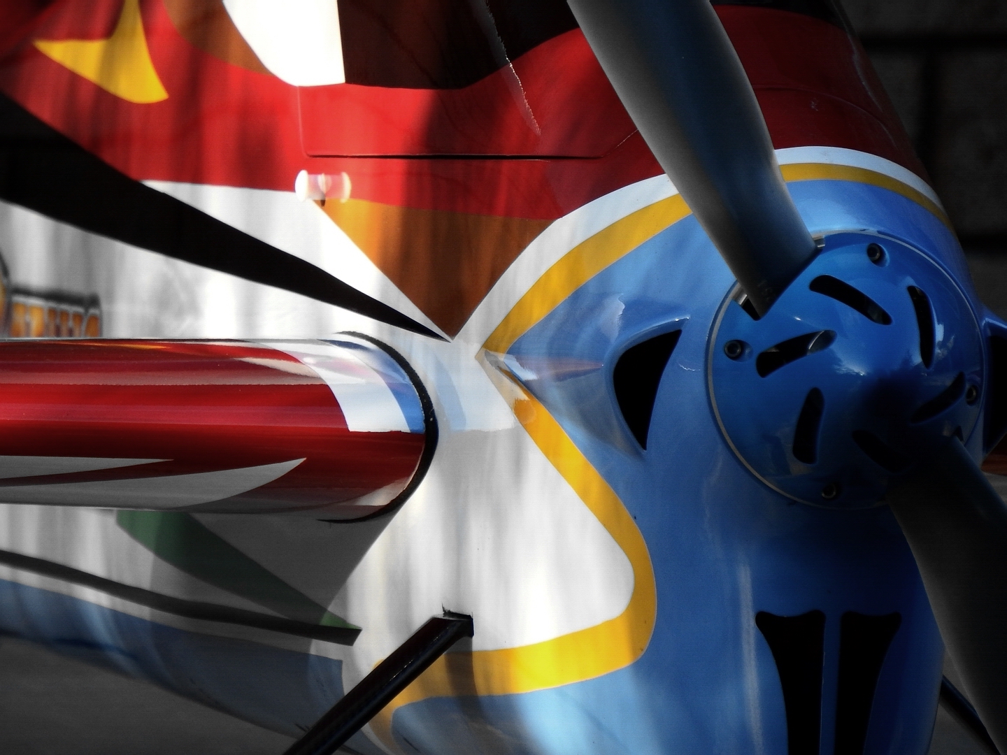
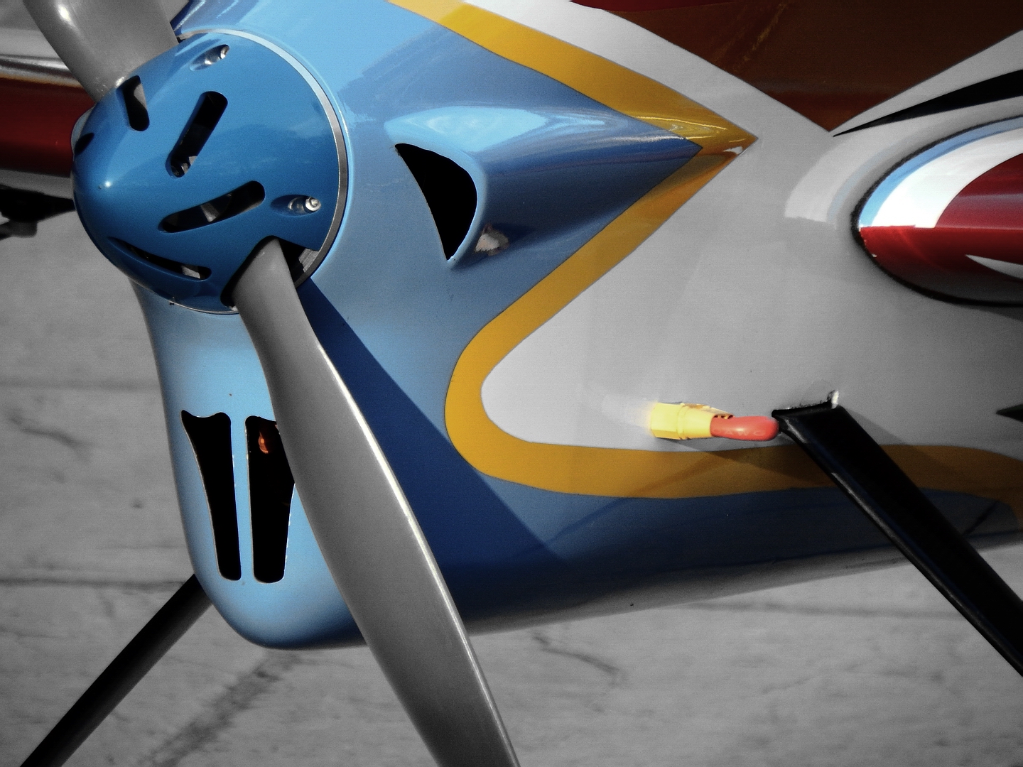
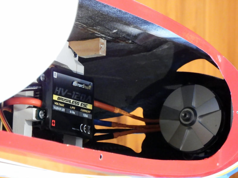
Front End:
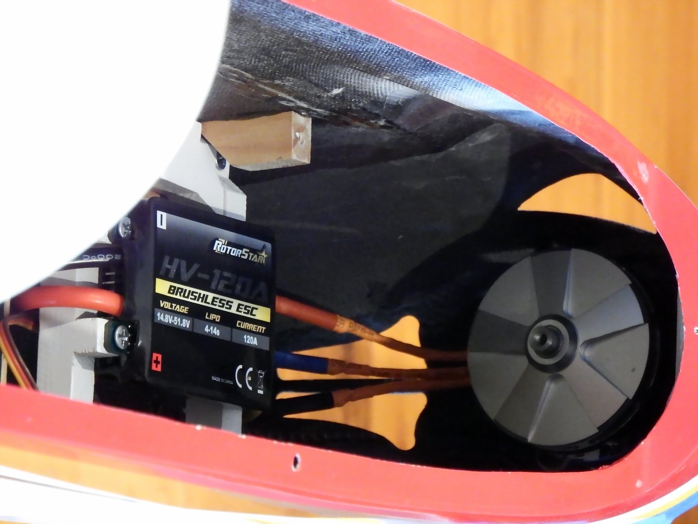
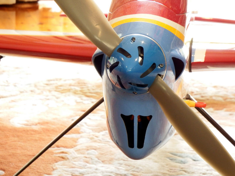
>>> The cowl is integral with the fuselage and coated on the inside with CF sheet.
>>> There is no pre-located motor mount. The owner is obliged to use the provided, unattached motor mounting, CF ring. The method I employed was as follows:
>> Front mount the motor/spider onto the CF ring.
>> While holding the motor/ring combo inside the fuselage, fasten the prop adaptor, Spinner and prop to the protruding motor shaft.
>> Shim and tape the spinner to the outside of the fuselage nose positioned as you would have it located permanently.
>> Using epoxy, tack the CF ring to the inside of the fuselage. Wait for that to set hard.
>> Now remove all the tape, shims, prop, spinner and motor components, leaving the CF ring tacked to the fuselage.
>> Fibreglass the CF ring thoroughly to the fuselage.
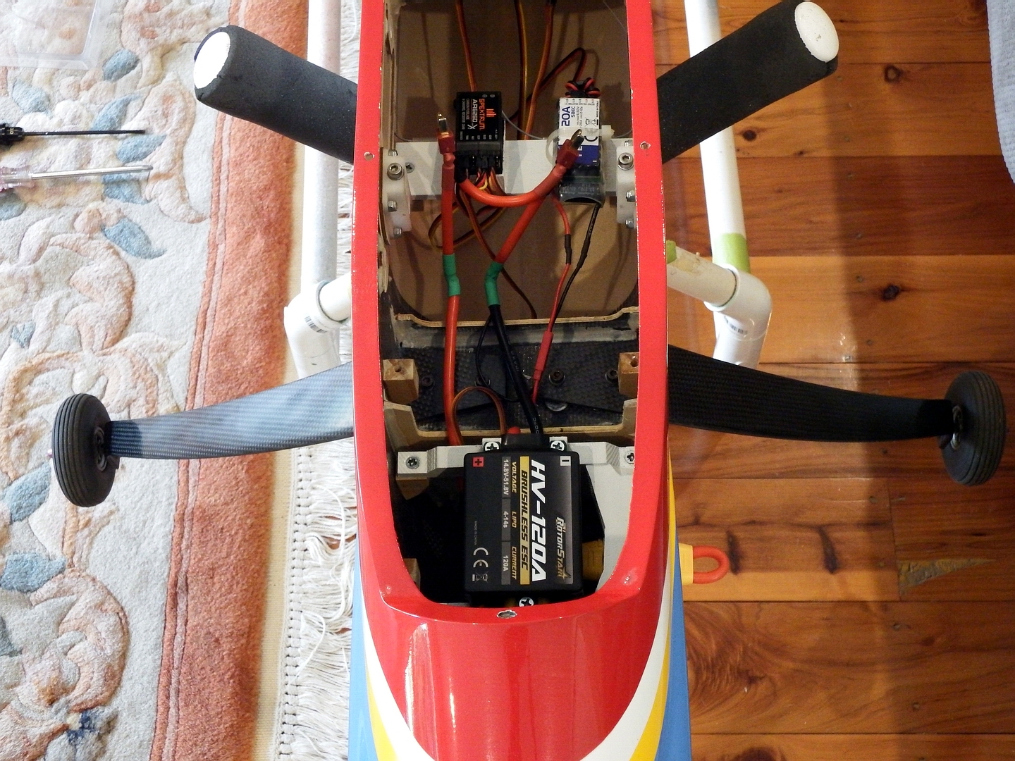
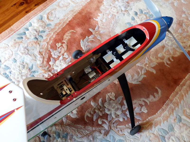
Under the Canopy:
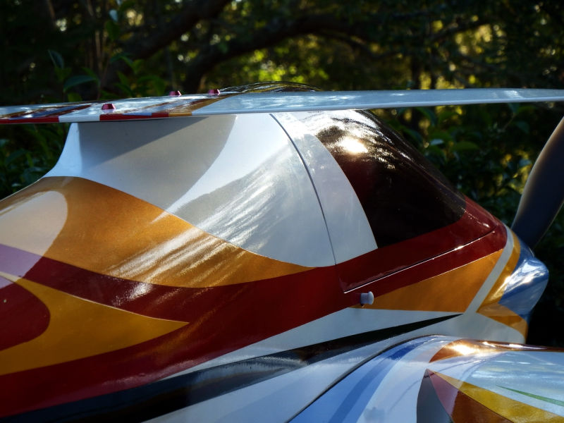
>>> I have not seen this type of canopy latch before. They comprise a long, round pin, attached to the canopy, which slides into a receiving hole in the fuselage edge. The pin is held in the hole by a spring loaded guillotine clip. There are release buttons on the side of the fuselage that release the pins when pressed. This assembly needs careful tuning and alignment to ensure the mechanism works faultlessly.
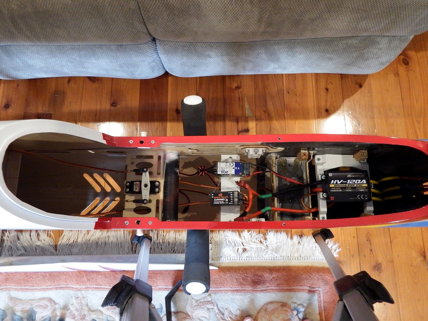
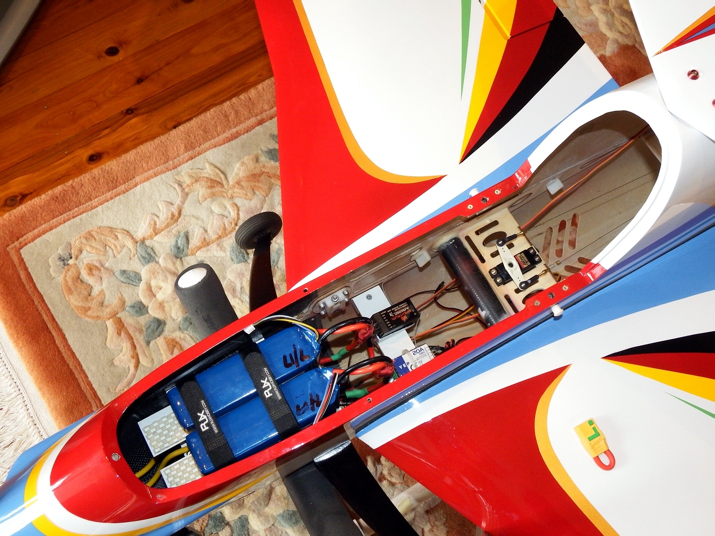
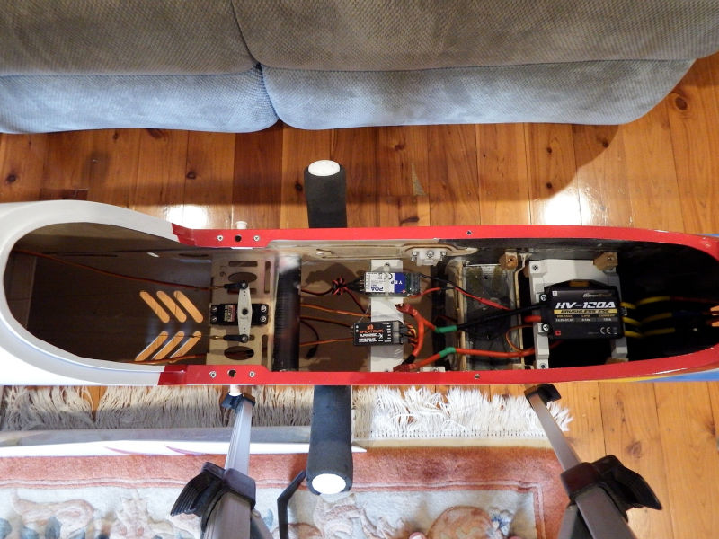
>>> The provided built-in battery tray was very light-weight and in the way of locating ESC and switches. The tray was removed. In its place I installed fuselage wall lugs and trays to support the ESC/Arming switch and battery tray. Both are now removable, held in place by 4 screws each.
>>> The opening to access the arming switch (XT90 type) from the outside had to be very carefully dremelled out.
>>> The wiring comprises series connectors for the 2 x 5S batteries, an integral arming switch - located below the ESC mount and hard fixed to this mount - and connection of the regulator (powering the receiver and servos) to one of the main power batteries via the arming switch.
>>> There is a removable tray aft of the battery/ESC/arming switch assembly. This tray supports the 23v regulator and 6 channel Rx.
>>> The rudder servo is mounted aft of the Rx/Regulator tray and joiner tube. This was the only mounting tray, originally supplied, that I retained.
>>> The battery tray comprises two cross members which screw to the fuselage lugs. There are then two longitudinal plates, joining the cross members, that support the batteries. There is lots of room to allow air to move around the batteries. The batteries are retained by two straps.
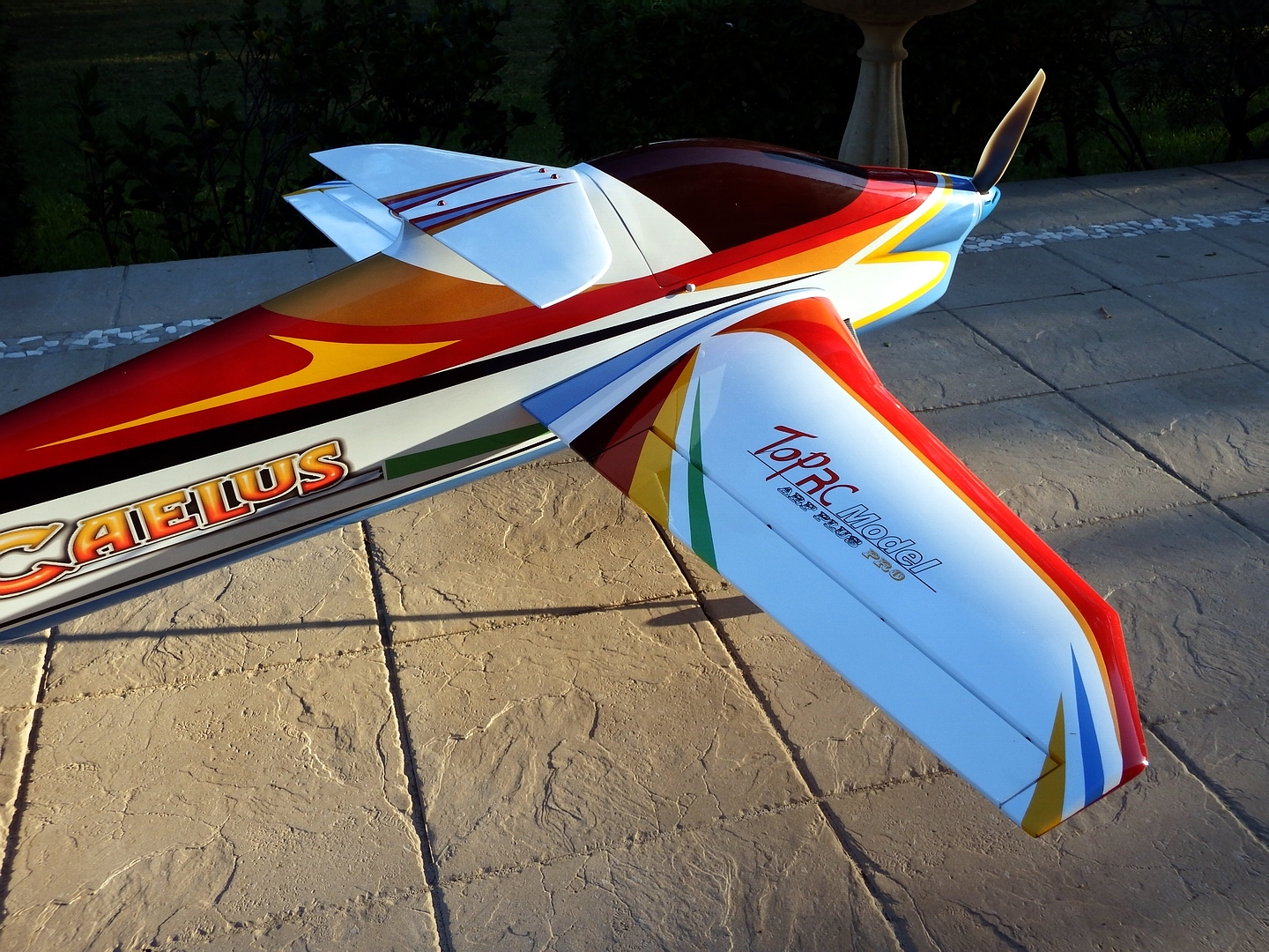
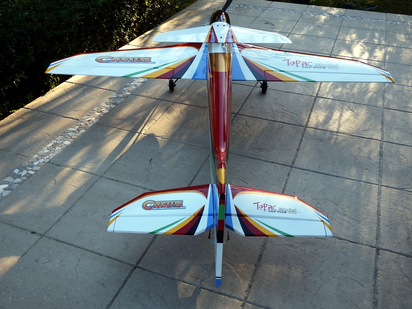
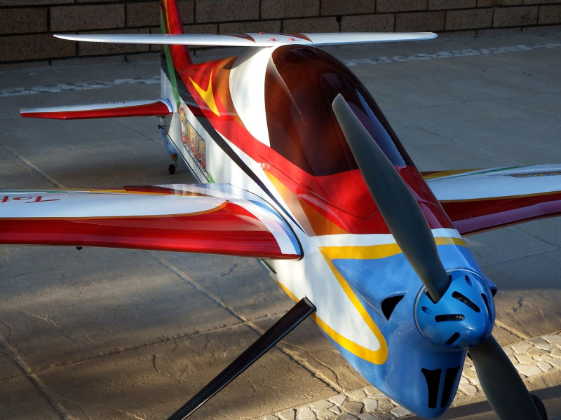
>>> The nose air inlet and shark gill air outlet grillages were designed, templated onto the surfaces and then very carefully dremelled out.
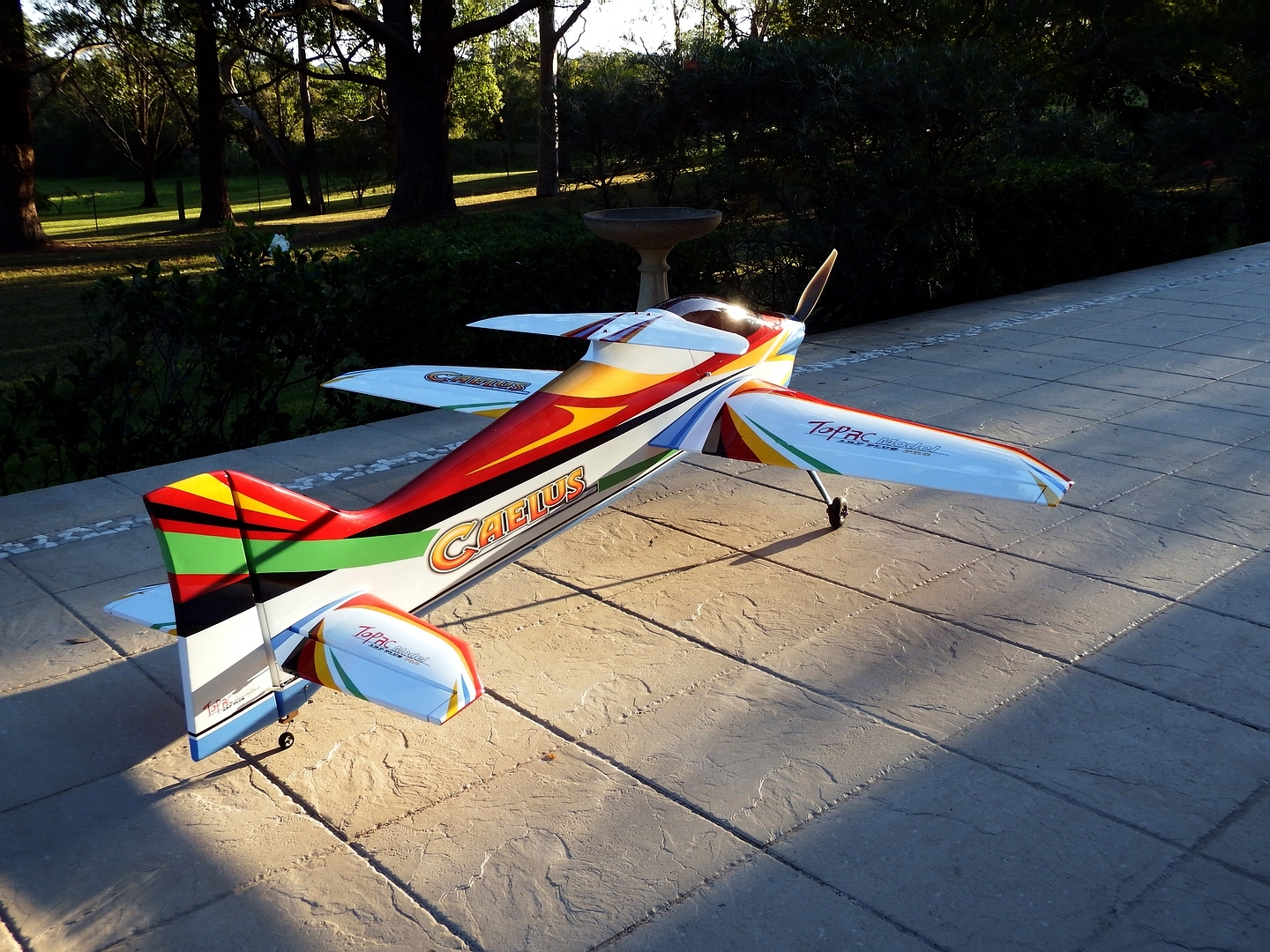
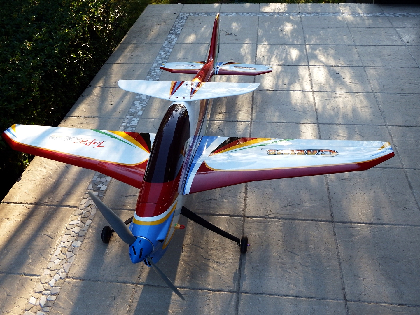
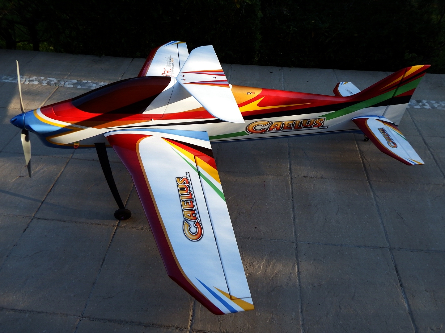
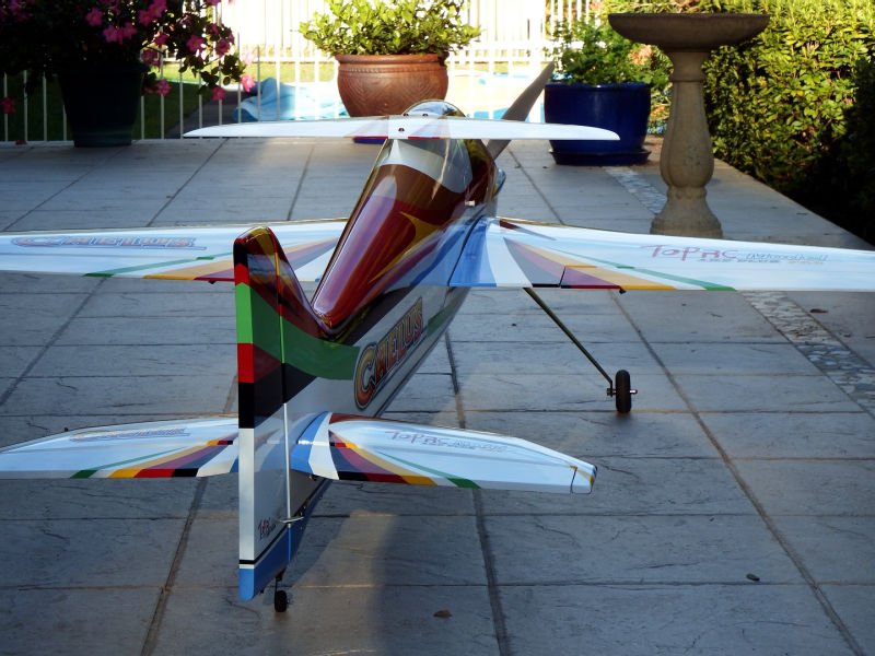
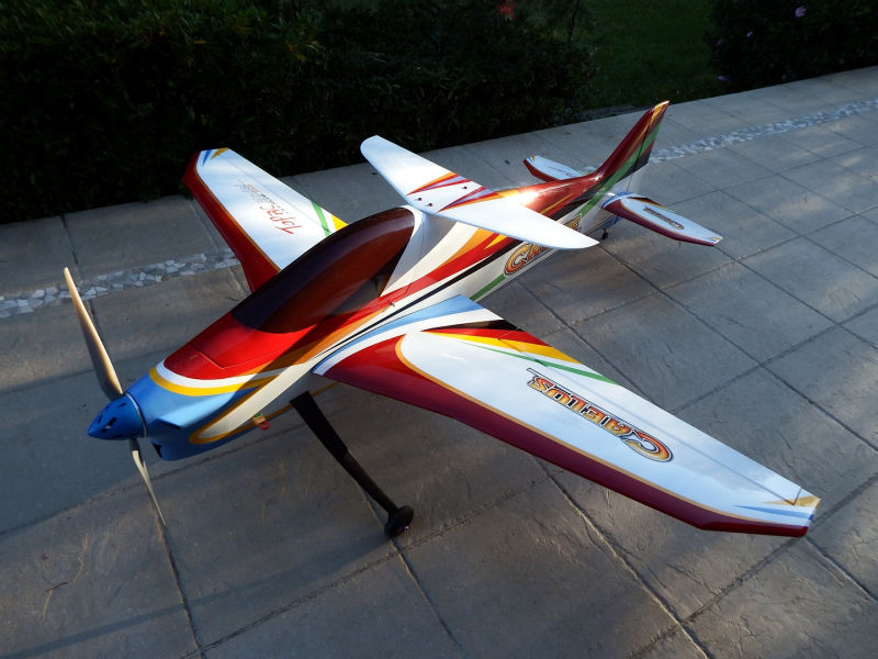
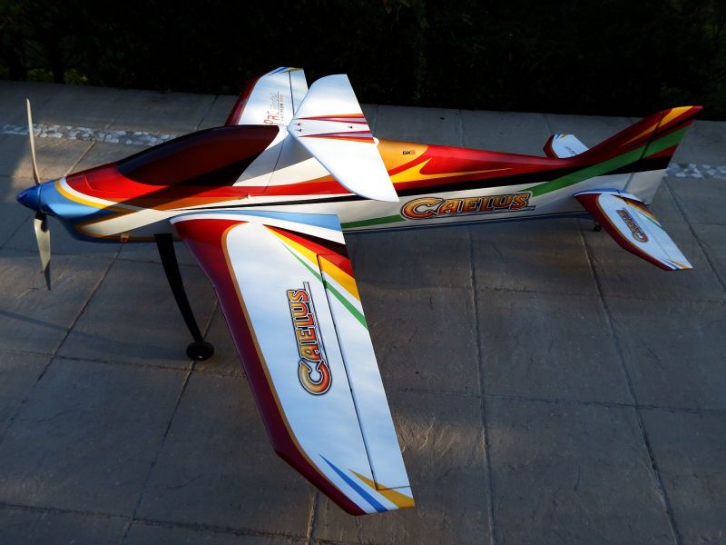
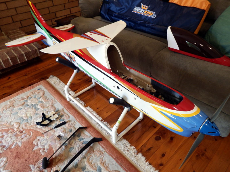
Overall Comments:
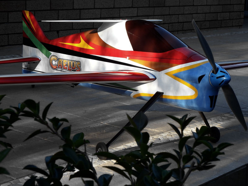
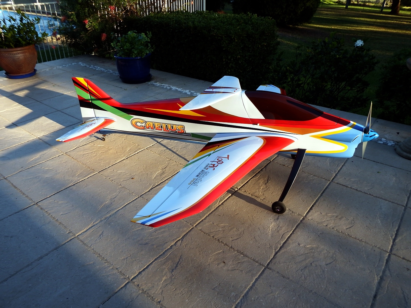
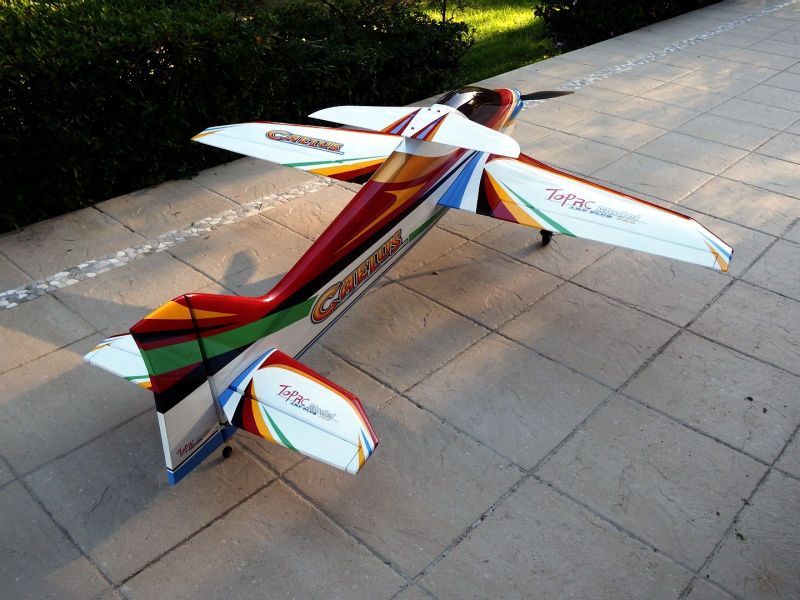
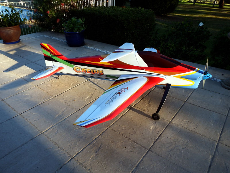
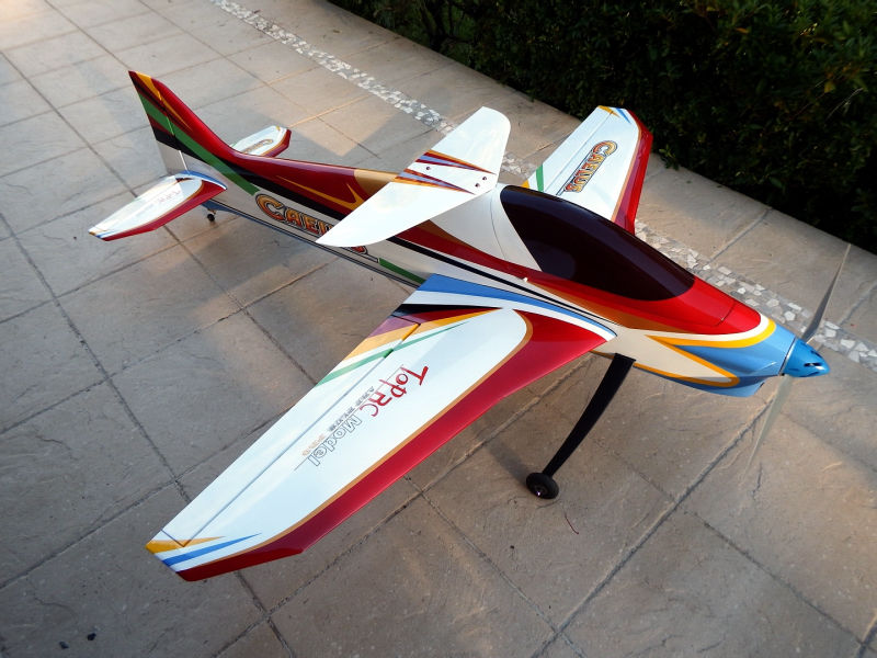
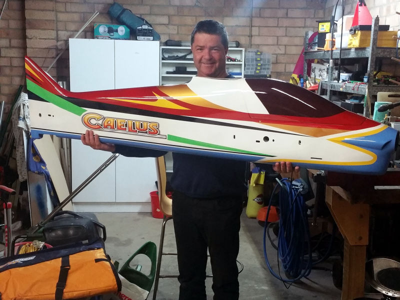
I have only a couple of composite planes like this one. Certainly the Caelus is the largest and most expensive. In the final analysis, the plane's finish is rather nice what with the all-over clear coat totally protecting the paint work.
Flight Review:
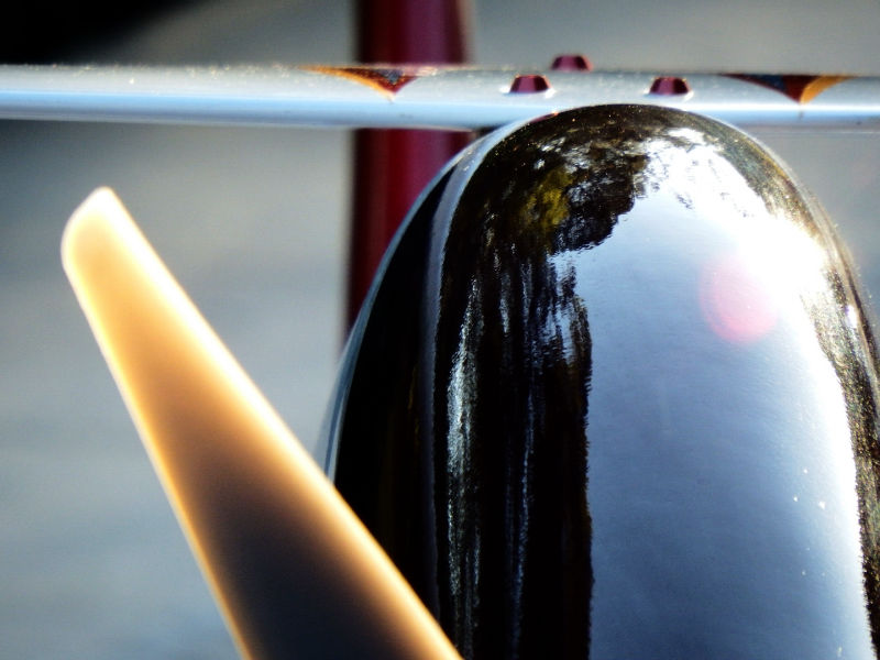
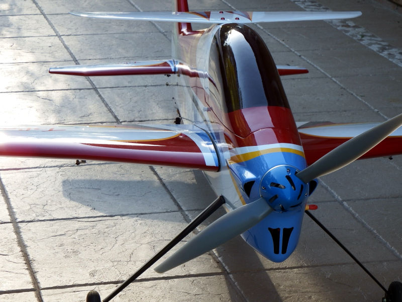
This plane has been in my hangar for 2 years as at June, 2018 having been flown around 50 times. As expected, it has that large plane ponderousness. Holds its line very well and knife edges superbly. In the interests of reducing resonant noise from the fuselage when knife edging or performing sharper turns, I intend changing out the two blade prop for a three blader. At some time I must do something about the undercarriage hold down in the fuselage - probably add another screw near the trailing edge of the U/C where it enters the fuselage.


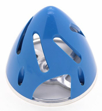
Source: Hobby King
Size: 82mm.
Aluminium-backed with draw holes in the nose to encourage air flow through the spinner and onto the motor.
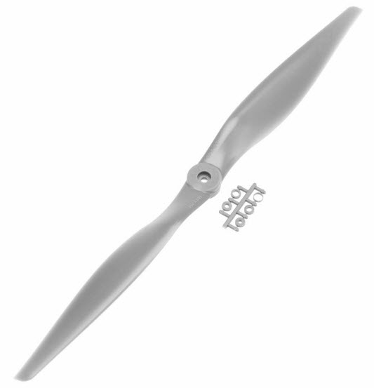
Source: RC World
Size: 20x10
Perfect size for our application according to eCalc - see above.
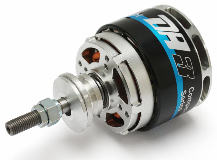
Model: Dualsky XM6355DA-12
Kv: 220
Max Power: 3096W max
Shaft Diameter: 8mm
Weight: 566g
As per the eCalc results, this motor will provide an easy 529watts per kg for this application.
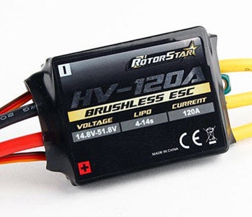
Model: Turnigy K-Force 120Amp Opto.
BEC: None
Programmable using the YEP ESC card.
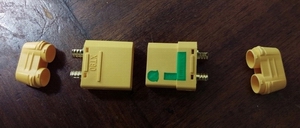
Model: XT90S with Spark Arrestor
Half connection has 6ohm resistor in series so there is no spark as the ESC capacitors load a charge. Nice soldered connection covers makes for a clean result.
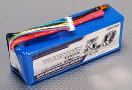
Two of these in series making up a power pack of 10S 5000 30C capable of producing 2700watts.

Technical images above show the straps in operation. Two are required to properly hold down 2 x 5S batteries.
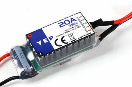
This YEP SBEC accepts up to 50volts input and up to 6v output. It is connected across one of the 5S batteries and is activated during the main battery pluggin.
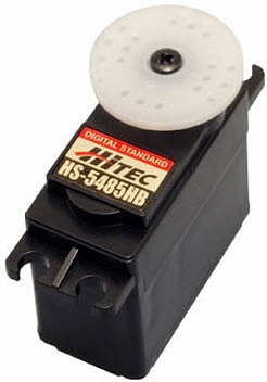
Model: Hitec HS-5485HB
Used for rudder and ailerons, this Karbonite geared servo will produce a stall torque of 6.4kg.cm at the intended 6v power supply.
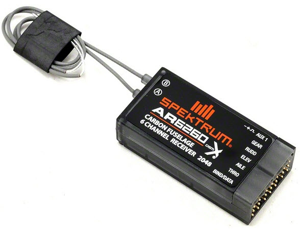
Model: Spektrum AR-6260
Modulation: DSMX
Especially designed for difficult fuselage applications, the long antennae provide for good reception coverage.
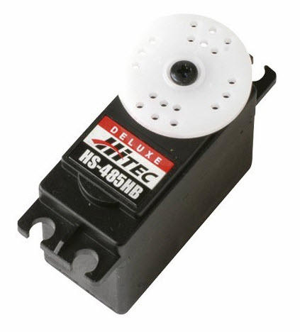
Model: Hitec HS-485HB
Used in the elevators, this Karbonite geared servo will produce a stall torque of 6.4kg.cm at the intended 6v power supply.

Model: Dubro Low Bounce 3"
These are ultra-soft tyres suitable for grass runways.
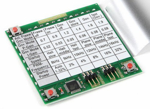
This card is suited to programming the RotorStar 120A ESC.

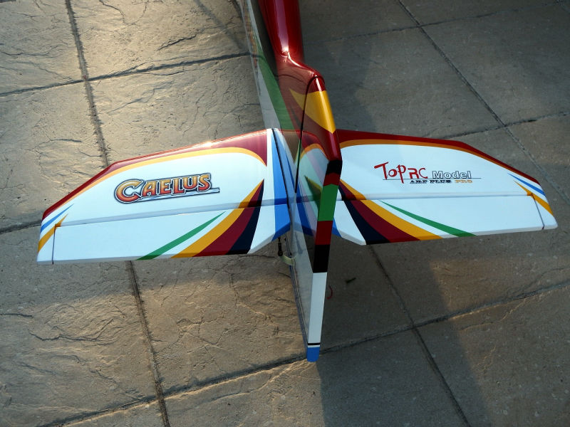
Ideal for caring for the wings. Includes extra pouches and a pocket for the joining tube.