The intention was to build a smoothly tapering wing with the following
features:
- No polyhedral.
- Add a 'D' box for torsional stiffness.
- Top and bottom rib capping.
- Ease the flat bottom, adding a slight turn up at the leading edge of the
ribs.
- Add ailerons.
- Add side mount (to fuse) bar to wing root.
|
|
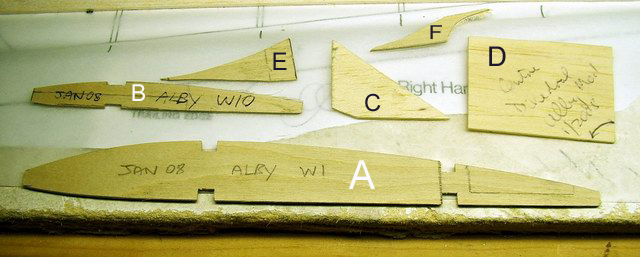
A - Plywood wing root template. Shaped approximately to rib W2. No
intention of using the rear spars!
B - Plywood wing tip template.
Shaped approximately to rib W10.
C - Right angle for checking ribs are installed vertically.
D - Root rib installation angle - less than as specified for the Albatross
which has a lot of dihedral.
E and F - Chocks used to shape the bottom sheet up to the rib leading
edge.
|
|
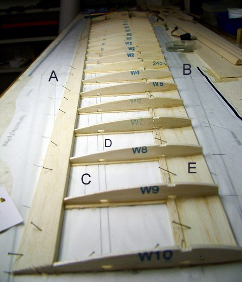
A and B - Notice the amount of original wing now excluded from the
construction.
C - Line indicating where the aileron will be cut from the completed wing.
D - Rear spar not used! Wing is to be 'D' boxed and rib-capped.
E - Bottom sheeting for 'D' box construction.
Notice the rib numbering. All the original ribs were used and just
reshaped using the templates (A and B above) to provide a smoothly
tapering wing. The 'Sandwich' technique was used to shape all the ribs at
the same time.
|
|
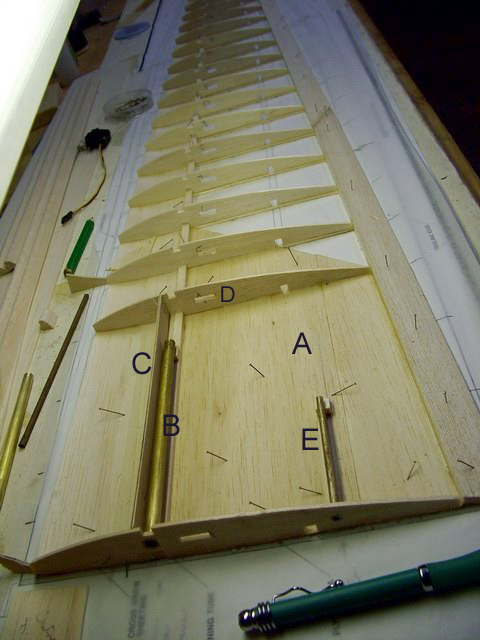
A - Bottom sheeting throughout near the wing root.
B - Brass tube epoxied between top and bottom main spars. The steel bar
(running through the tube) connects the two wings and transfers load
between the wing and fuselage.
C - One of two plywood shear transfer pieces either side of the brass
tube. This transfers wing connection load to the wing spars and sheeting.
D - These holes out to rib 12 allow a servo control wire to be installed.
The servo will be installed close to the aileron.
Can you spot a problem at ribs 10 and 11?
|
|
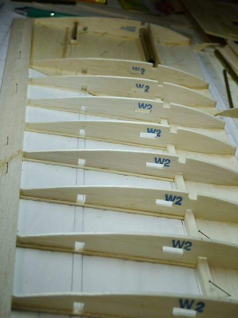
Another view of the wing with bottom sheeting, rib caps and servo cable
hole. |
| |